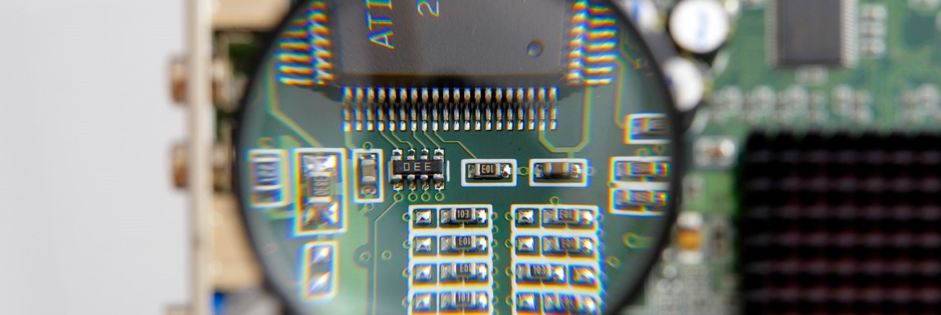
Maintaining and improving quality
Fuji has the right solutions
for resolving quality issues
"We are wanting to improve quality, but are not seeing any results."
"We have put measures in place, but productivity dropped."
Is your production site facing any such quality-related problems?
Fuji provides solutions for maintaining and improving quality without sacrificing productivity.
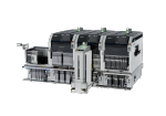
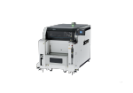
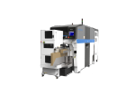
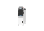
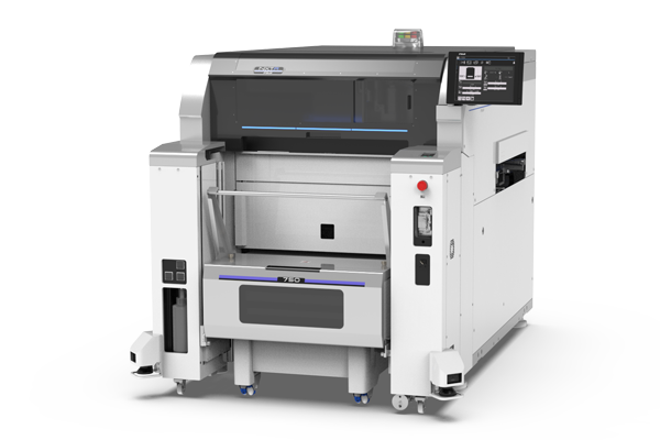
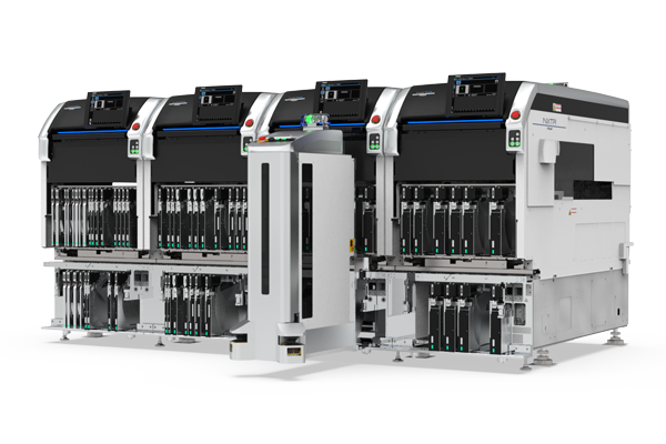
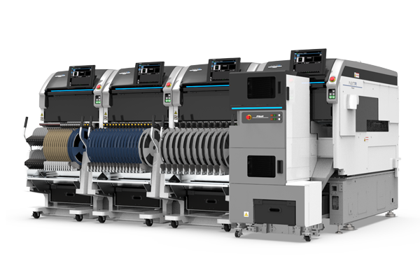
Applicable machines: NXTR pick and place machine, and NXTR PM printer
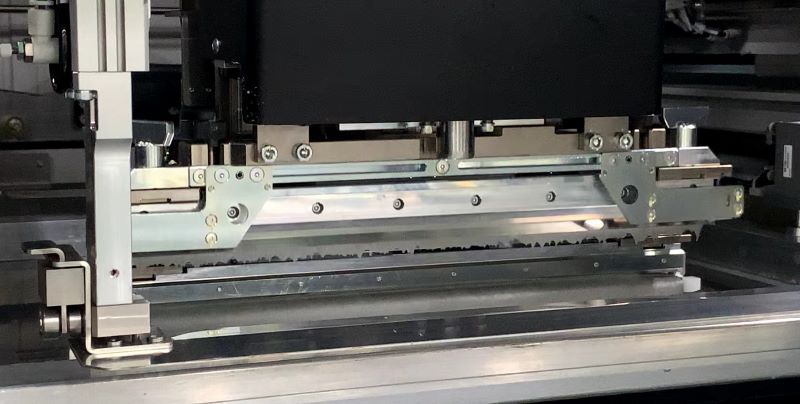

Solder printing process
Have you ever had the experience of running a successful test printing, only for the printing quality to deteriorate during actual production?
Such an event is likely being caused by changes in the characteristics of the solder, the machine configuration, or quality issues in manual work.
View solutions by issue
Issue
The amount of solder transferred is unstable: Unwanted solder deposits and smearing
Favorable printing conditions can be maintained by inhibiting the formation of unwanted solder deposits and smearing that are the cause of poor metal stencil to panel contact, while suppressing changes in the solder and metal mask.
Close
Maintaining the condition of the solder
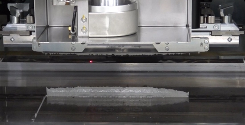
Solder roll control prevents air from entering into solder rolls
By controlling the operation to raise the squeegee after printing, it is possible to reduce the amount of hanging solder affixed to the squeegee, keeping the amount of air that enters into the solder roll to a minimum.
Squeegee operation is specified based on the individual production program, making it possible to cater to high-mix production styles.
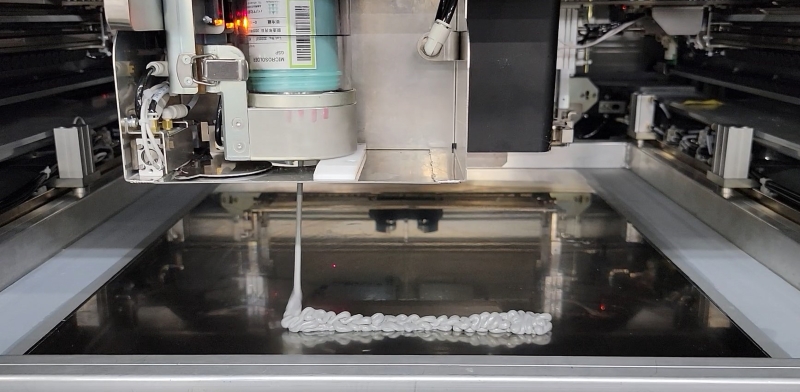
Solder roll measurement and automatic supply prevent insufficient solder transfer
The solder roll atop the metal stencil is measured at regular intervals, and solder is supplied when needed. Since the solder is always at the optimal volume for printing, it is possible to prevent defects caused by insufficient solder transfer.
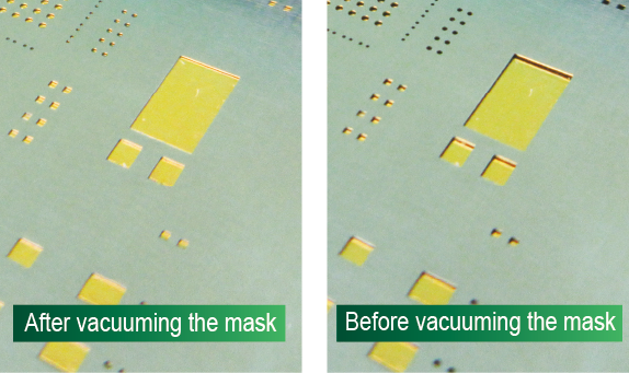
Holding the metal stencil improves contact between the metal stencil and panels, keeping smearing under control
By using vacuum pressure on the metal stencil to improve the level of contact between the metal stencil and panel, smearing can be kept under control. It also prevents printing defects that result from curvature in the metal mask.
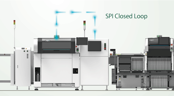
Enabling feedback from an SPI machine to a printer makes it possible to perform the right action automatically based on the results from the SPI
Inspection results are received from the SPI, and the appropriate response to trends that show a change in conditions can be performed automatically. Because these changes are responded to before they lead to defects, high-quality solder printing is maintained.
- Automatic mask positioning adjustment
- Automatic cleaning
- Solder supply
- Machine stops
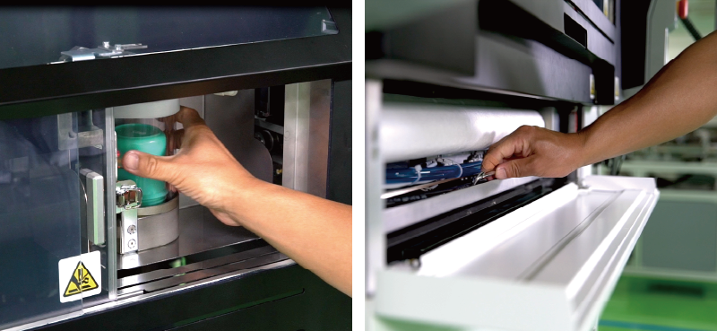
Non-stop solder and cleaning paper exchange means that the machine covers stay closed, to maintain a consistent internal temperature.
Solder cups and cleaning paper can be exchanged through a door in the front of the machine while production is ongoing. The door through which these materials are exchanged is small, keeping temperature fluctuation to a minimum, which in turn helps to maintain the state of the solder, for stable transfer amounts and high-quality printing.
An optional temperature controller can be used to further stabilize the internal temperature of the machine.
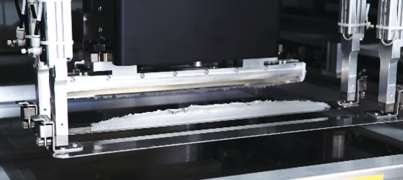
Solder collection and transfer can be utilized to ensure printing with a stable solder roll shape even after changeover
Solder collection and transfer inside the machine keeps the solder roll intact during transfer, for stable printing quality from the very first panel.
Solder collection and transfer makes up a large portion of changeover work at the printer, so automating this step goes a long way toward reducing workloads.
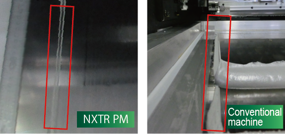
The paste doctor prevents solder from escaping
The mechanism to reduce the amount of solder escaping from the printing squeegee lowers the volume of escaped solder substantially. This leads to a higher rate of utilization of solder. While this results in using fresh solder which furthers the stability of print quality, it also reduces solder collection and cleaning work.
Close
Issue
The desired printing accuracy cannot be achieved: The positional accuracy is not stable
To be able to achieve positional accuracy and printing accuracy that remains stable over a long period of time, it is necessary to have a configuration that includes a precise positioning correction mechanism and a highly rigid structure that is not impacted by changes in printing speed and printing pressure.
See details
Built to deliver high-accuracy printing
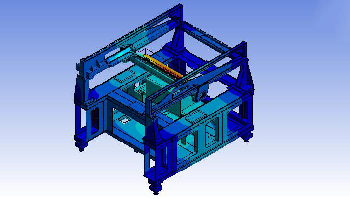
High-rigidity frame table for supporting high-accuracy printing
Consistent highly rigid machine design from the base to printing section maintains print quality and enables high accuracy printing over a long period of time, whether printing ultra fine patterns for 0201 mm (008004") parts, or those of large panels.
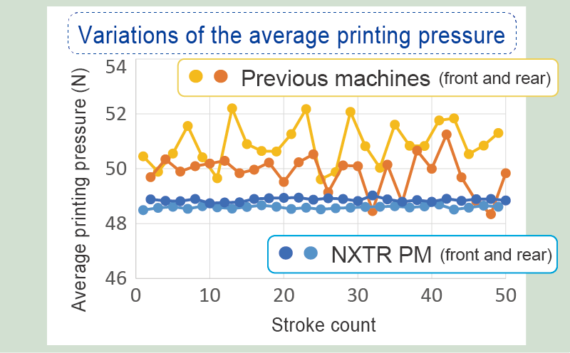
Printing pressure feedback control for ensuring consistent pressure
Our realtime print pressure feedback control and newly developed squeegee head are employed to maintain the angle of the squeegee edge at all times. This ensures stable solder shape and deposit volume during printing.
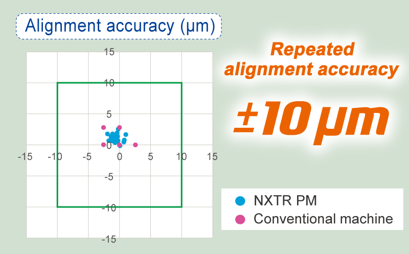
New frame holder structure and high resolution camera support high positioning accuracy
The industry's highest level of repeatable plate alignment accuracy of ±10 μm (6σ) has been achieved by using a high-resolution camera to improve mark image recognition accuracy and creating a new frame holder structure for metal masks. Highly accurate positioning with precise correction capability ensures stable print quality.
Close
Issue
Operational errors: Material setting mistakes
By automating tasks that are traditionally performed manually, there no longer needs to be a reliance on the skills of the individual, while also preventing careless mistakes from happening.
See details
Automation of changeover work
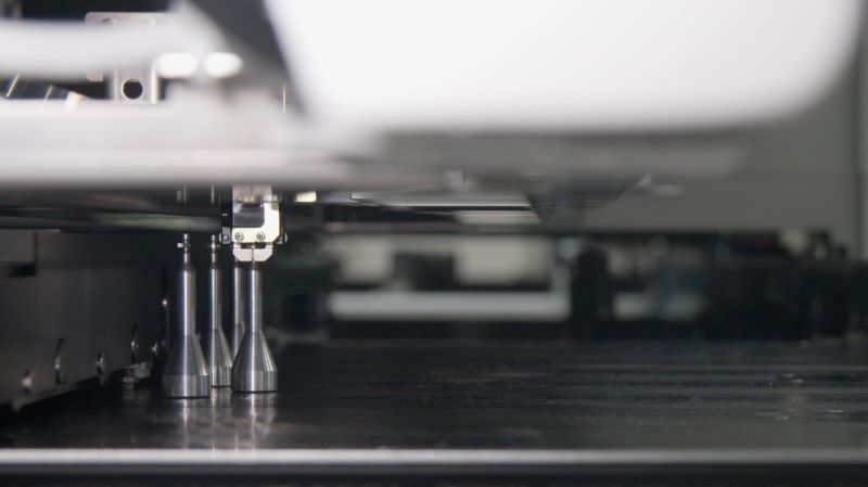
Automatic backup pin positioning cuts down on changeover time
The backup pins used to support panels are positioned automatically while the printer is in operation, according to the positions specified in the production program. This prevents pins from being positioned incorrectly and reduces the workload on operators.
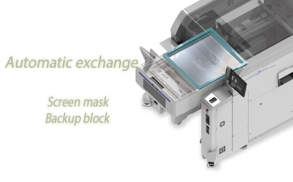
Automatic exchange of metal stencils and backup blocks by PM Smart Changer
By setting the metal stencils and backup blocks to be used in the next production to the PM Smart Changer, these items will be exchanged automatically during changeover. This reduces the workload on operators and eliminates reworking that may result from human error.
PM Smart Changer introductionClose
Close
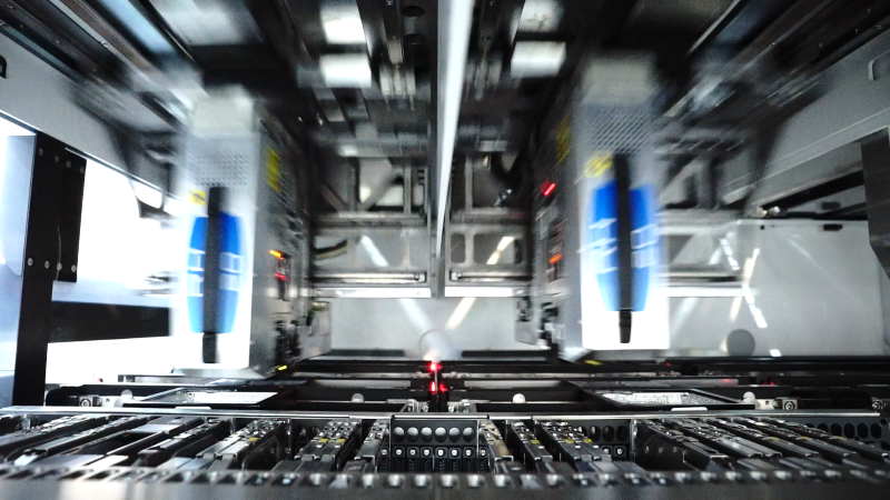

Part placement process
It can be a concern when experiencing worsening pickup rates, error stops at a machine, and drops in equipment performance as these may in turn lead to quality issues, and thus need to be remedied quickly.
It is important to address these types of issues before they occur in order to maintain high quality.
View solutions by issue
Issue
Unstable placement quality and placement stance: Poor pickup stance, dropping or damaging parts during transport, and crushed solder
Using the latest in sensing technology, the series of processes from pickup to placements is checked to accurately recognize the state of the materials being used, so that parts can always be placed using the optimal placement pressure.
Close
Part and material condition checks
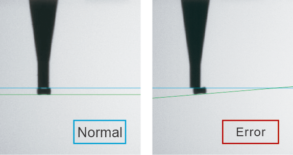
Checking all nozzle tips from the side using the intelligent parts sensor
To prevent defects from occurring, IPS can be used for a wide range of checks at the nozzle tips, from part pickup stance to parts remaining on nozzles, as well as upside-down checks for minimold parts.
- Checks for tombstoned parts and up-side down parts
- Part thickness checks
- Placement height correction
- Checks for dropped parts and parts remaining on nozzle
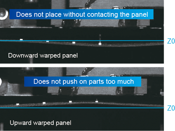
Placement height adjustment ensures that parts are not affected by changes in the placement surface height
The placement stroke follows changes in the placement height due to panel warpage and distortions, enabling placement of parts using the appropriate level of pressure.
For upward panel warpage: Excess pressure exertion on parts and panels during placement is prevented
For downward panel warpage: Placement deviations caused by mid-air placements is prevented
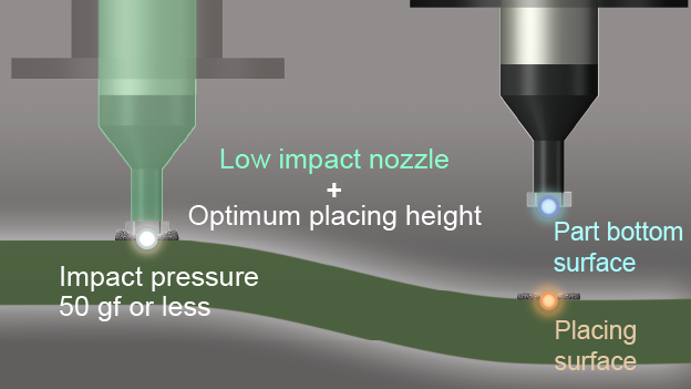
Adjust the placement height according to the panel warpage by using panel height detection
The panel warpage is automatically measured by a laser sensor before parts are placed. Placement is only performed on panels that are within the set tolerance, so that defective panels are stopped before they can be produced. The intelligent parts sensor, in conjunction with Fuji's low-impact nozzles, works to prevent damage to fragile parts and solder bridging.
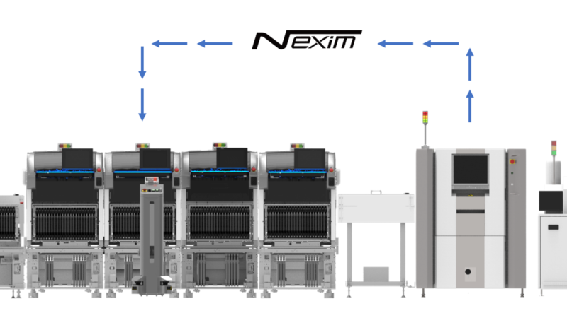
Automatic correction of placement positions based on AOI inspection results
If inspection results received from the AOI show a trend for a change in accuracy, the positioning is corrected automatically.
Because these changes are responded to before they lead to problems, high-accuracy part placement is maintained.
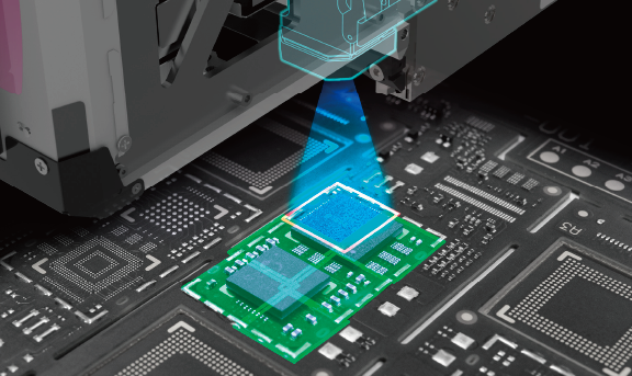
Check placement within mounter modules with the MPI function
Placement areas can be checked inside the pick and place machine to check the placement quality of certain parts and to check placed parts before shield cases are placed over top of them.
In addition to preventing an increase in defective products, placement sequences are skipped on boards on which defects have been detected, so that time and materials are not wasted.
Close
Issue
Using the wrong parts or defective parts: The wrong parts are set or misshapen parts are used
Checks are performed for part setting mistakes or misshapen parts inside the machine before placement to ensure that the wrong parts and defective parts are not used. The necessary steps are taken before defects can occur, negating the necessity for rework and preventing discard losses.
See details
Detecting setting mistakes and eliminating defective parts
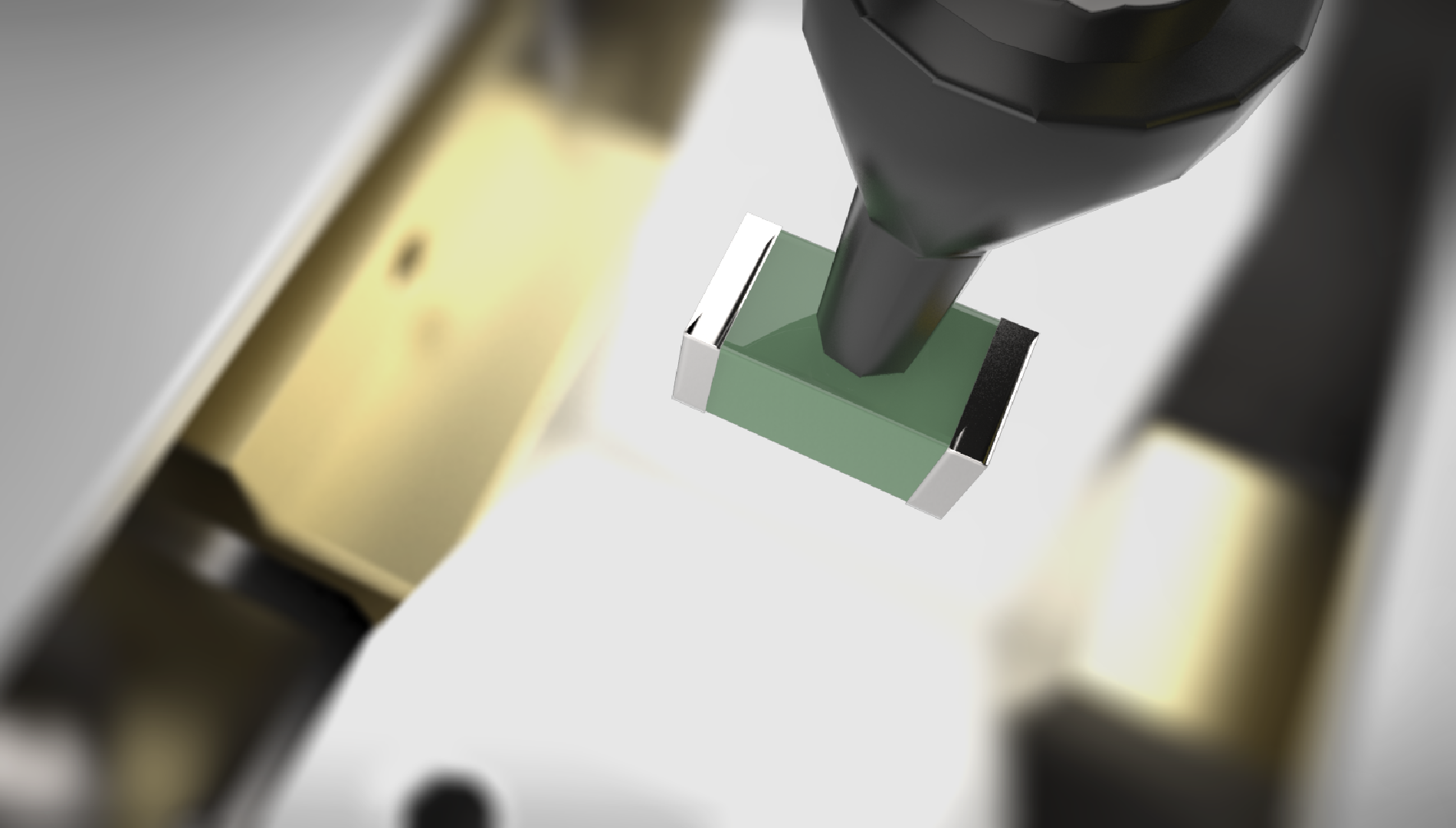
Preventing parts with the wrong electrical properties from being placed using LCR checks
This function is used to check the resistance, inductance, and capacitance of chip parts inside the machine. Because parts are checked inside the machine after the parts are set but before placement is performed, any setting mistakes will be detected.
Measurement timing
- When starting and resuming operation
- When resupplying parts
- When performing a sampling check
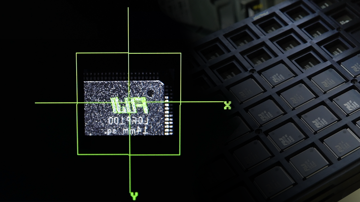
Preventing placement defects caused by setting mistakes using Top View Recognition (TVR)
The machine is able to recognize characteristics on the top of the part before pickup, preventing the types of placement errors that setting mistakes might cause.
TVR function introduction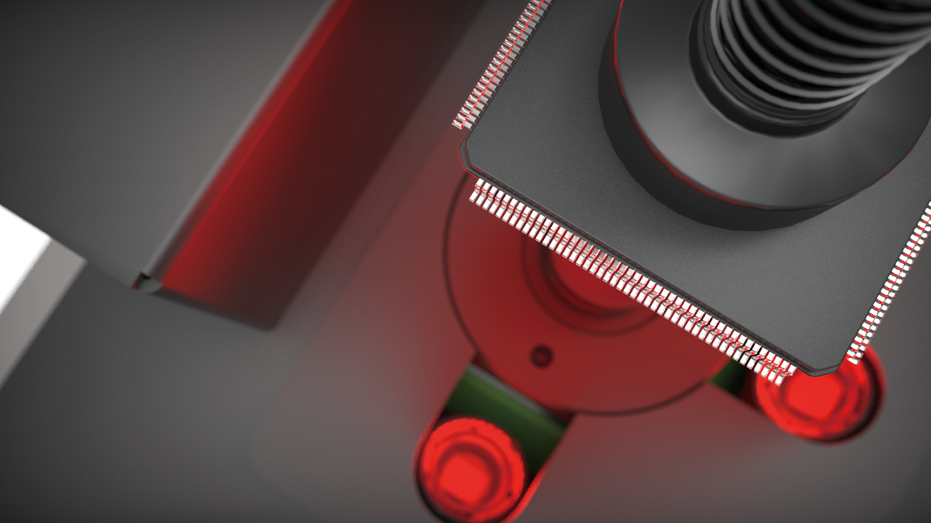
3D coplanarity check that checks for misshapen parts and removes them
3D coplanarity detects problems with packages and connector leads, and problems with the bumps on BGAs and CSPs. Because this method even detects problems in the Z direction that are difficult to detect using part imaging cameras, it is possible to prevent the use of parts likely to cause connection issues.
Check points
- Lead shape
- Missing and collapsed bumps
Close
Issue
Drops in machine performance: Manual workloads, management workloads, dependence on certain individuals for maintenance work, dust problems inside the machine
Equipment needs to be kept in top condition to be able to produce high-quality products. This means that maintenance of feeders, nozzles, and heads, along with a remedy for dust generated when peeling cover tape, are indispensable.
See details
Automating maintenance work and management
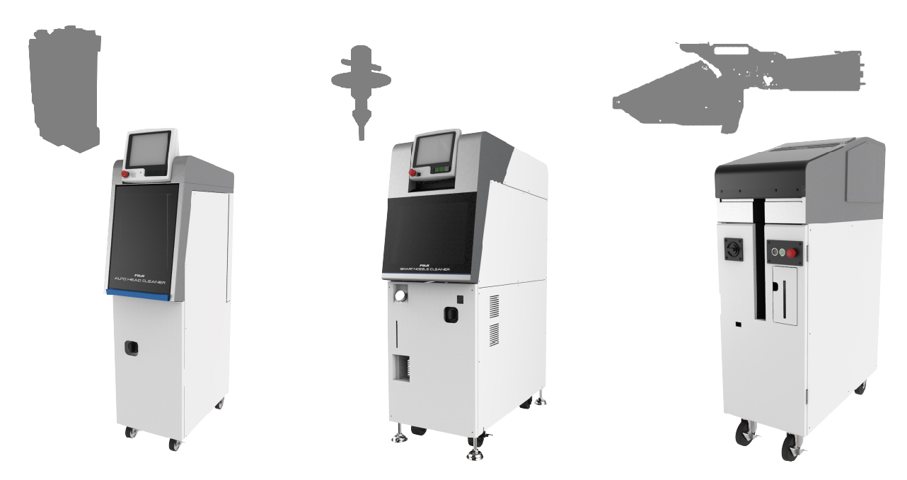
Automatic maintenance units are for easy maintenance that does not rely on individual skills, supporting a multi-skilled workforce.
Fuji's placement machines feature easy, toolless configurations for exchanging heads and other units. Fuji's automated maintenance units make it possible for anyone to perform maintenance work on removed units in the same amount of time and with the same level of quality. Removed units can be exchanged with another unit, making it possible to continue production, and thus being able to perform maintenance while keeping drops in operation rate at the production line to a minimum.
Automatic maintenance unit introduction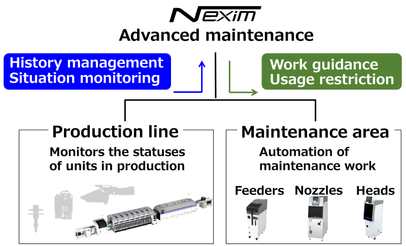
Automating maintenance on the management side with advanced maintenance
Data such as the pickup rates and usage time for the feeders, nozzles, and heads being using in production are collected. Once a unit has reached a predetermined threshold for use or a drop in the pickup rate, it is flagged for maintenance. Follow the guidance provided for maintenance work to keep your equipment in top condition for production with little effort.
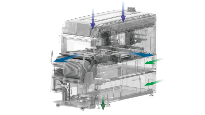
Increased machine internal pressure and airflow design for keeping the inside of the machine clean
The airflow inside NXTR has been designed so that dust generated inside the equipment is dispelled from the machine.
The level of dust that adheres to nozzles and products is reduced, contributing to both the maintenance and improvement of quality.
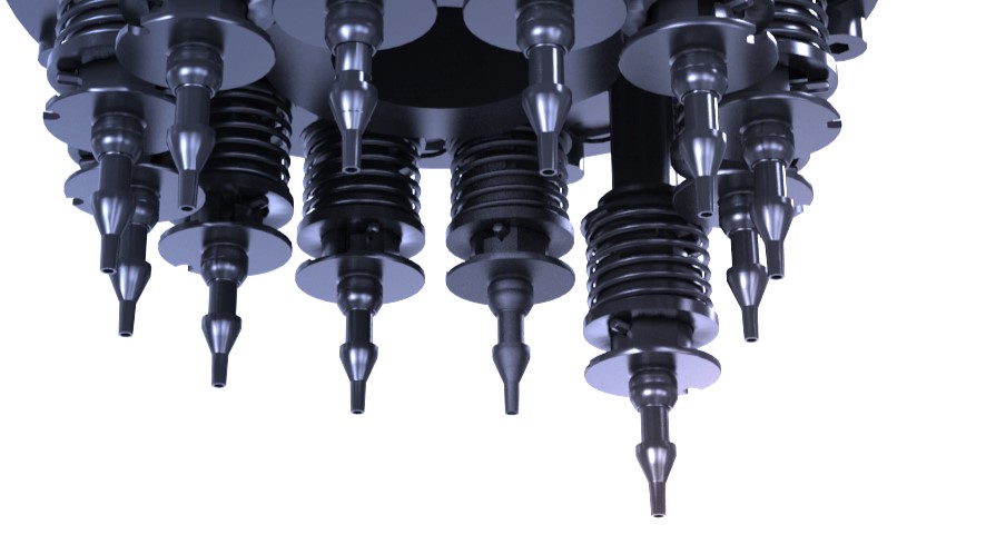
Skipping nozzles that are in poor condition by using the nozzle statistical warning function
When the nozzle in use reaches the set pickup error count, the machine is stopped to prevent further problems. If replacement nozzles are set in the nozzle station, defective nozzles are automatically replaced with the replacement nozzles without stopping production. This makes it possible to keep drops in productivity to a minimum while maintaining quality.
Close
Close

