


Using Top View Recognition to Prevent Part Setting Mistakes
There are times when an operator may set the wrong part type or set parts in the incorrect supply direction when supplying parts to the machine.
For example, when setting trays to a tray drawer there can be cases in which the incorrect parts are set or the supply direction may be wrong such as when a tray is set in the wrong direction or if someone has returned parts that have come out back into the tray by hand.
These kinds of mistakes can cause bad placements or machine stops due to vision processing errors, leading to poor product quality and delays in production. This will also result in reworking or the disposal of produced products. Normally, the bottom of a part is vision processed and the part type and supply direction are checked based on the image of the bottom of the part. However, there are many part types for which it is not possible to differentiate between them because they do not have any characteristics that can be used to determine type and direction on the bottom of the part.
Fuji provides methods for solving these problems with Top View Recognition (TVR). TVR makes it possible for the machine to recognize characteristics on the top of the part before pickup, preventing the types of placement errors that setting mistakes might cause. This article explains two of the major focuses of using TVR.
Recognizes the specific characteristics and determines whether the part can be used
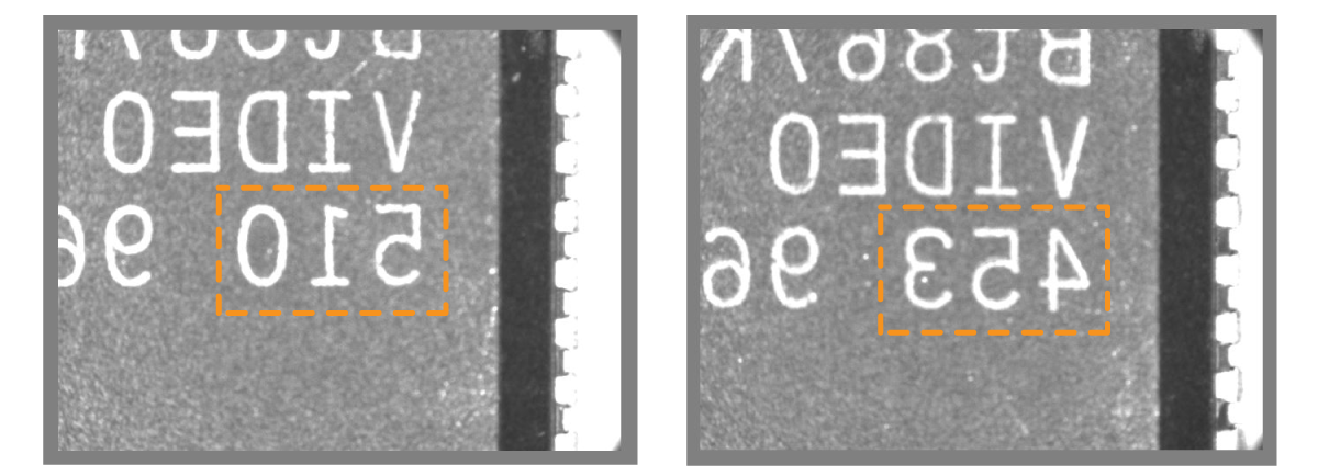
Manages the part lot by verifying inscriptions
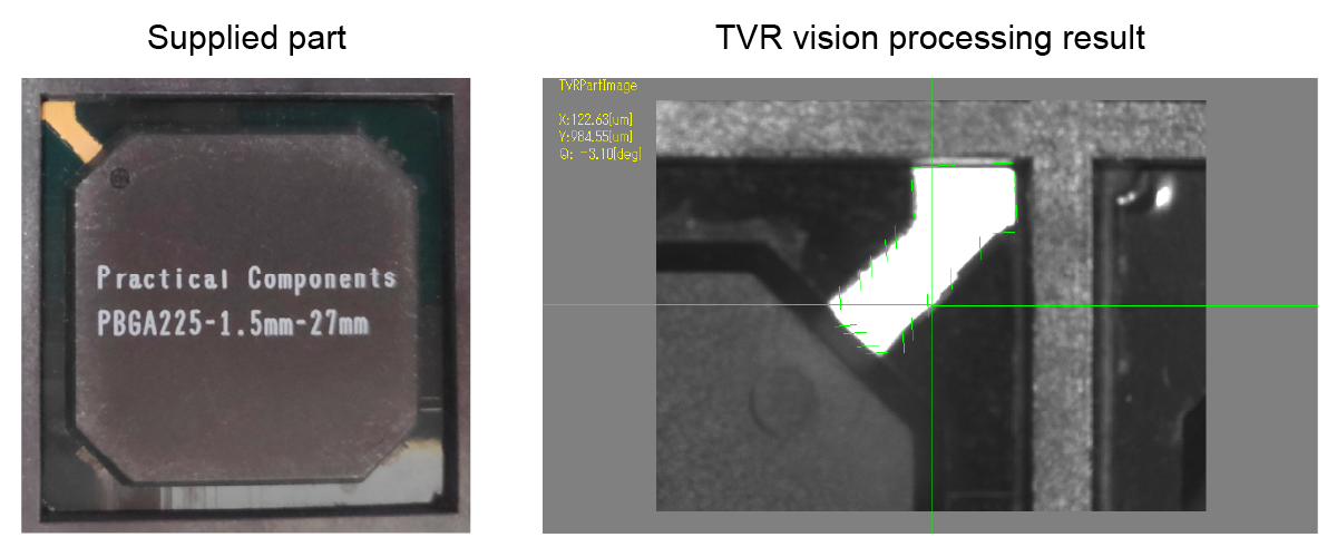
The characteristics on the top of the part are recognized, and the conformity of the part supply direction is determined.
By doing this, even if the supply direction is incorrect, parts can be placed at the correct angle. (See note)
Note: It is possible to select between angle correction, skipping pickup, and stopping the machine.
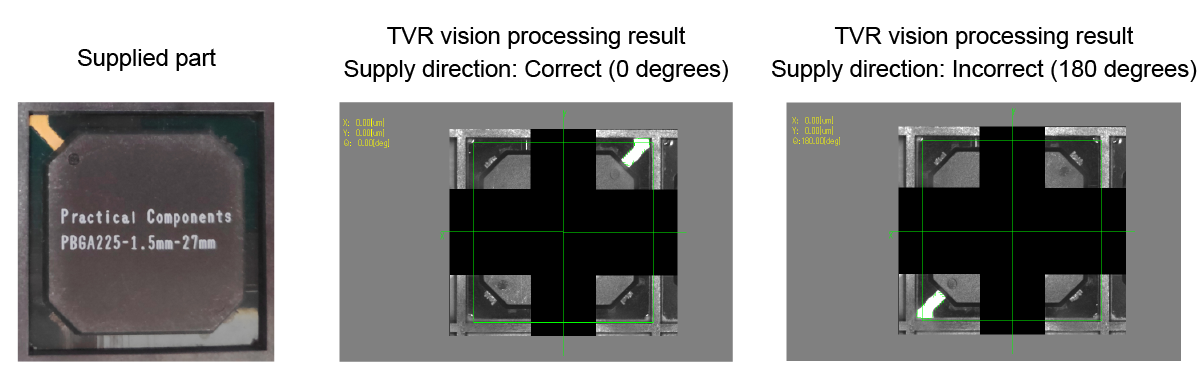
Determining the conformity of the part supply direction
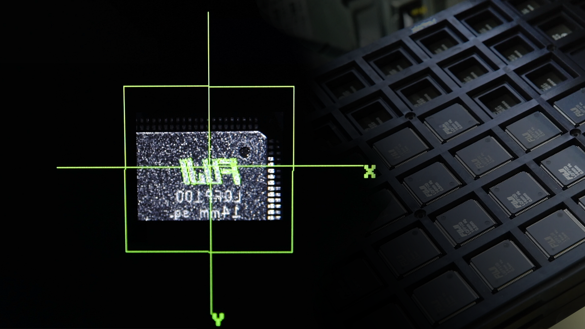
Laser inscribed markings can be difficult to image clearly depending on the camera angle and the way the light hits the markings. This makes discerning those markings during vision processing difficult.
Attaching a low angle lighting unit to the machine makes it possible to have inscribed marking show clearly during imaging.
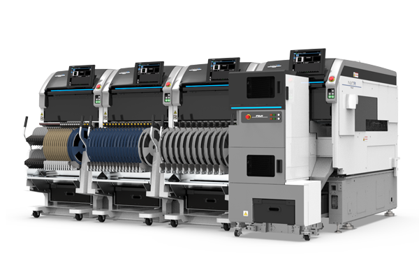
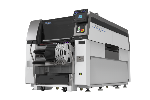
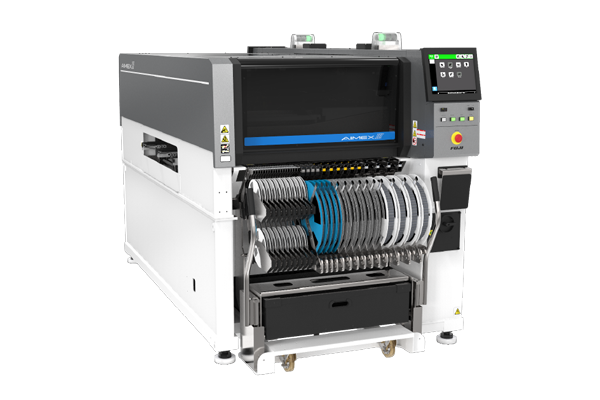
Applicable machines: AIMEX III, AIMEX IIIc (Custom support is available for AIMEX IIS)
Note: Supported part supply units are Fuji intelligent feeders, tray unit-LTW, and tray unit-LTW2
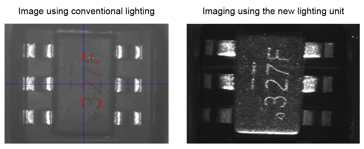
Inscribed markings are imaged more clearly using the new lighting unit
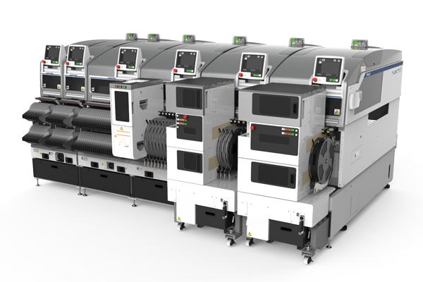
| Machine types | NXT III / NXT IIIc / AIMEX III / AIMEX IIIc
(Twin robot/single robot) |
NXTR S model / NXTR A model / AIMEXR
(Twin robot) |
|---|---|---|
| Head type | H01 / H02(F) / OF / H08M / H12HS / V12 / H24系 / DX(S1/R4/R12) | RH28 / RH20 / RH08 / RH02 / RH01 |
| Part supply units*2 | Not specified | Not specified |
| Part size | Based on the head specifications
Recognition target: 6 x 6 mm or less |
Based on the head specifications
Recognition target: 6 x 6 mm or less |
| Verification timing | Feeders: The first part only
Trays: Select between only the first part, or all parts |
Select between only the first part, or all parts |
| Machine types | NXT III / NXT IIIc / AIMEX III / AIMEX IIIc
(Twin robot/single robot) |
NXTR S model / NXTR A model / AIMEXR
(Twin robot) |
|---|---|---|
| Head type | H01 / H02(F) / OF / DX(S1) | RH02 / RH01 |
| Part supply units | Not specified | Not specified |
| Part size | Based on the head specifications
The direction mark size must be less than 6 x 6 mm |
Based on the head specifications
The direction mark size must be less than 6 x 6 mm |
| Supply direction | 0, 90, 180, 270 degrees | 0, 90, 180, 270 degrees |
| Verification timing | All parts | All parts |
Please note that these specifications have some limitations and may vary by version. Contact us for details.