


Placement solutions for panels used in communication infrastructure
5G operations are now in full swing all around the world, and production of 5G base stations is proceeding at a rapid pace.
Stability and improvements in processing capability are sought from 5G base stations and servers so that large data loads can be processed without delay. The electronic panels and electronic parts used in data processing are becoming larger and heavier in order to support the high-speed processing of large volumes of data and higher performance, and the SMT process must be able to respond to these changes.
Here we will introduce placement solutions that are necessary for the production of 5G base station and server boards.
Electronic parts: Larger CPU components and increased memory capacity for increased processing capability
Electronic panels: Increases in size in accordance with the attachment of sub boards, and larger parts and multilayering to increase the processing capability
Increase in production volume and product types
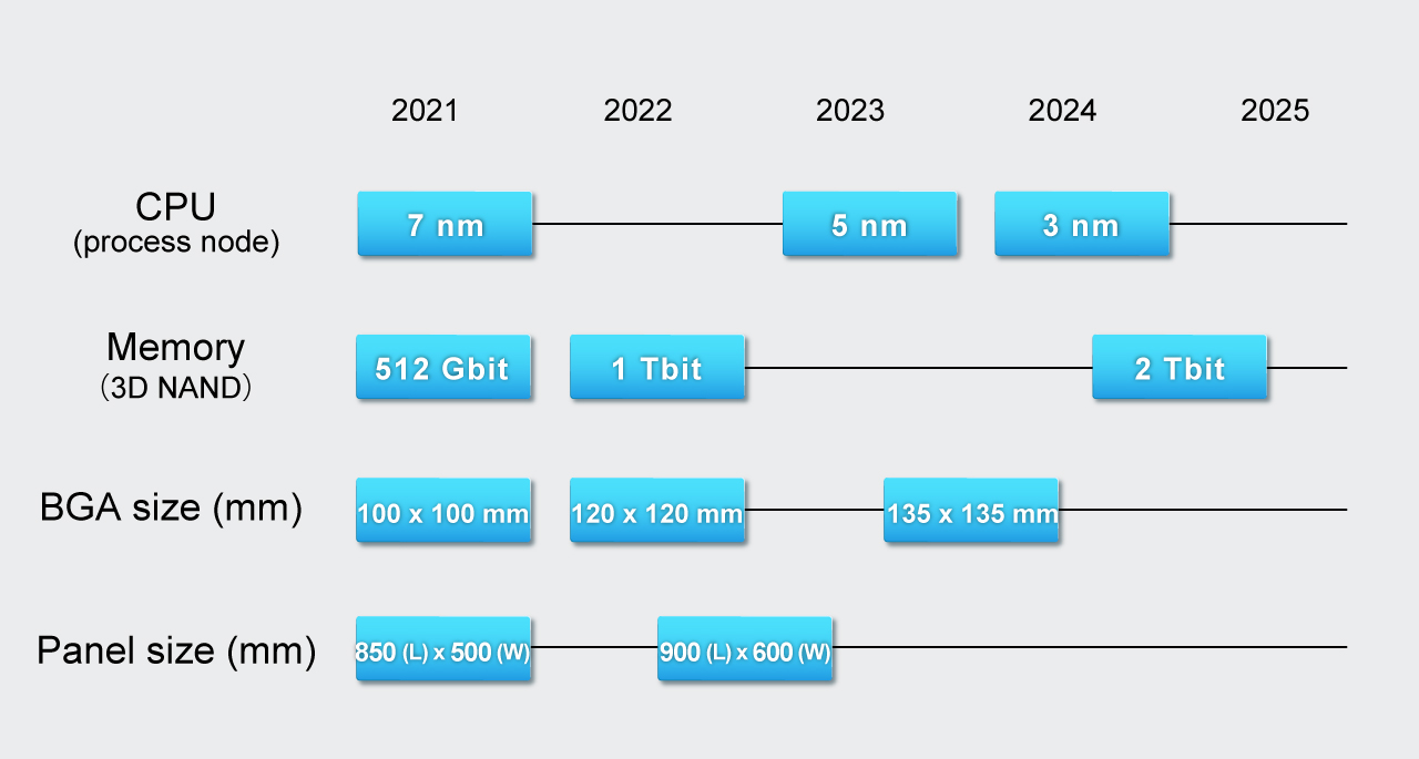
Projected trends for 5G components
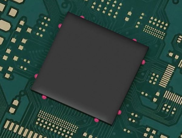
As the performance of CPUs has improved, packages and socket parts have become larger and heavier.
Here we have solutions for reliable pickup and placement of these larger and heavier parts.
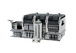
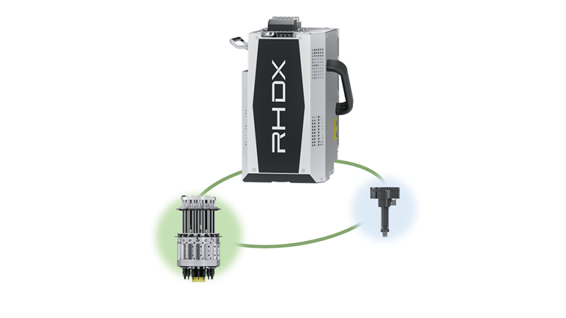
Reliable pickup and placement of increasingly heavy parts - DX head S1 tool
The S1 tool for the DX head can stably pick up and place parts weighing up to 250 g.
It is possible to have in-line production of key parts such as CPU packages, which are becoming larger and heavier.
Note: The transportable weight is different depending on the part shape.
Prevent defects during secondary melting - DX head glue tool
The gluing process for specific parts does not have to be a dedicated stage, but instead applied in the placement stage. An effective solution for preventing large BGAs and unstable odd-form parts from coming off or falling over during secondary melting.
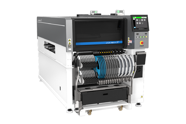
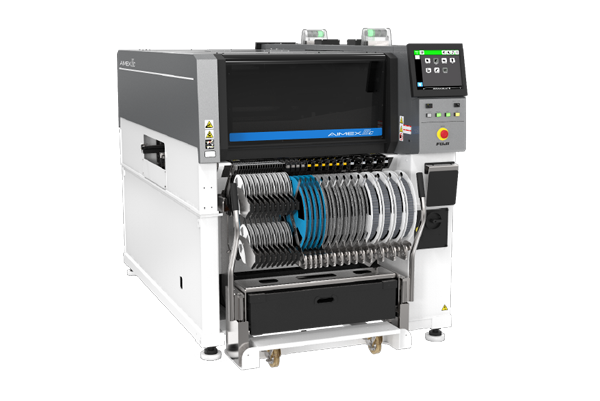
Note: Applicable machines: AIMEX III、AIMEX IIIc
Secure holding and accurate positioning of odd-form parts - Custom nozzles and chucks
It is possible to create custom chucks and nozzles to ensure secure holding of odd-form parts and heavy parts that have little clamping surface and clamping allowances.
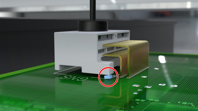
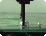
Pressure insertion of large connectors - Pressure placement
Parts with insertion pins such as large connectors can be reliably inserted in one go. Insertion pressure of up to 100 N can be used.
Applicable heads: DX-S1, H01, H01V, H02, H02F, OF
Supported range: 3.5 to 100 N
Reduce manual insertion processes - Pushing placed parts
Parts such as large connectors with many insertion leads and shield cases that are difficult to be inserted at one time can be reliably inserted by pushing multiple locations to mitigate the stress applied to the part.
Applicable heads: H01, H01V, H02, H02F, OF
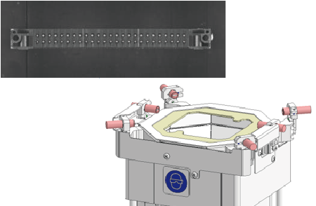
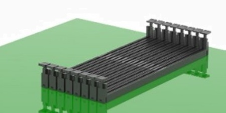
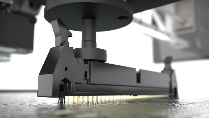
Image recognition of all insertion leads - Sidelight camera
It is possible to recognize the lined-up insertion leads of DIMM sockets and large connectors to reliably insert these parts.
Large parts are imaged in sections, to perform image recognition of all insertion leads.
Electronic panels for communication infrastructure are becoming larger with more layers in order to support high-speed processing of large amounts of data and multi-functionality. However, there can be issues after reflow such as warping of the panel, leading production sites to devise various methods to stabilize placement quality, taking the characteristics of the panel into account.
Here we will introduce placement solutions for warped panels.
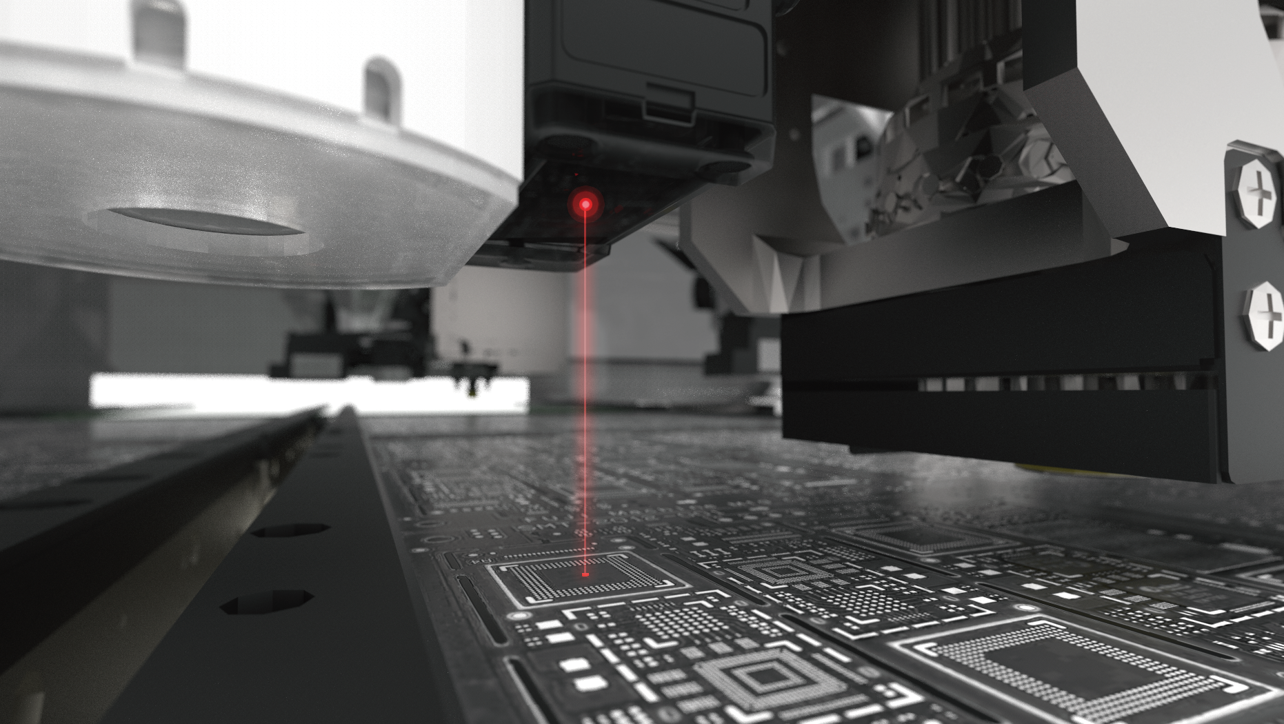
Adjusting the placement height according to the panel warpage - Panel height detection
By measuring the panel warpage and offsetting the part placement height, it is possible to control stress on parts during placement and prevent solder bridging.
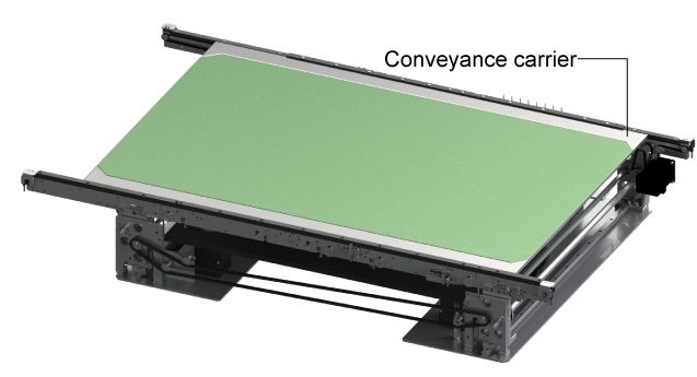
Supporting greater weights corresponding to larger panels and carrier conveyance - Conveyor for heavy panels
We are seeing an increase in the weight of both panels and the carriers used to transport large panels to control warping, and thus support for conveying such heavy panels is required.
Fuji's conveyors for heavy panels are capable of conveying panels up to 12 kg.
Catering for panel warpage after reflow - Custom conveyors
With customization that works with the characteristics of the panel, it is possible to reliably place parts even on panels with a large degree of warpage.
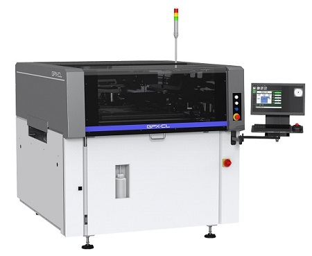
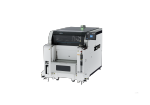
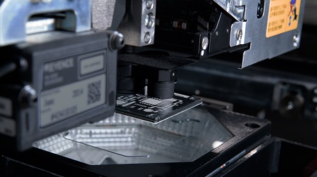
Supporting solder printing for large panels - GPX-CL
GPX-CL
The large table loaded in the printer makes it possible to print solder on large panels, often seen with dimensions of 850 x 610 mm, used in 5G base stations.
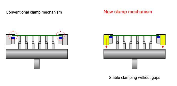
Always the right clamp strength - Clamp based on the panel bottom surface
The newly developed clamping mechanism based on the panel bottom surface ensures that panels can be supported and clamped. The shifting of panels caused by external forces such as printing pressure is reduced, leading to improved print quality.
As product types continue to increase, changeover work is becoming more complex and work time is increasing. To be able to complete work in a timely manner, it is necessary to make work routes and operator tasks as simple as possible.
Fuji provides solutions for keeping changeover time to a minimum.
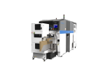
Non-stop changeover - Multi Job Line Balancer AB mode and tray changeover mode
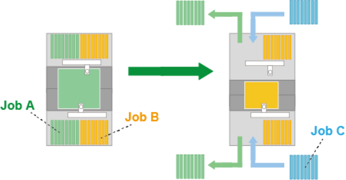
Multi Job Line Balancer AB mode
Feeder pallets are divided into two sections. Production is performed using the feeders at one section, enabling changeover at the other section without stopping production.
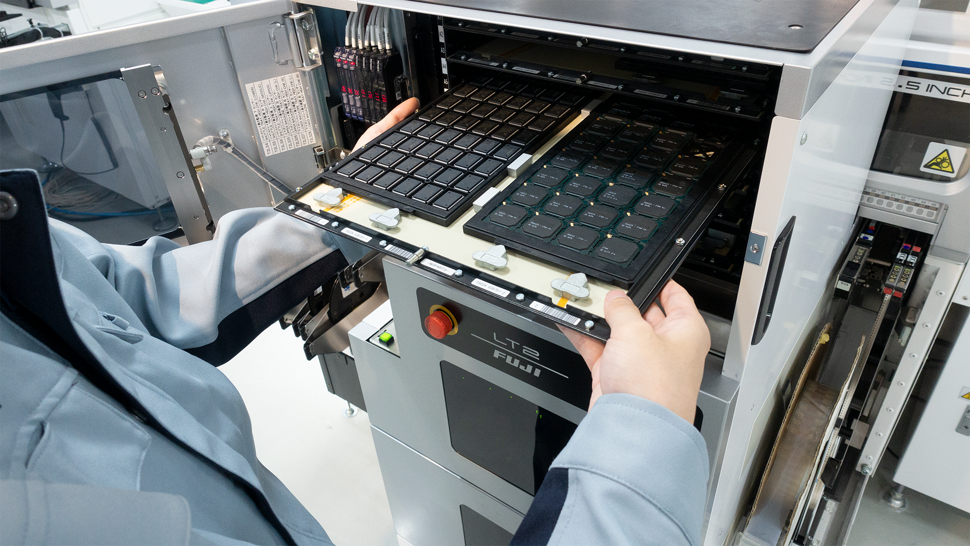
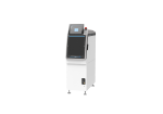
Tray changeover mode
By taking advantage of two tray magazines, one on top and the other below, one magazine can be used for production while the other magazine is in the retracted position, and can be used to exchange parts ready for the next production.
Minimizing changeover time through grouping and batch exchange - Production collecting differences
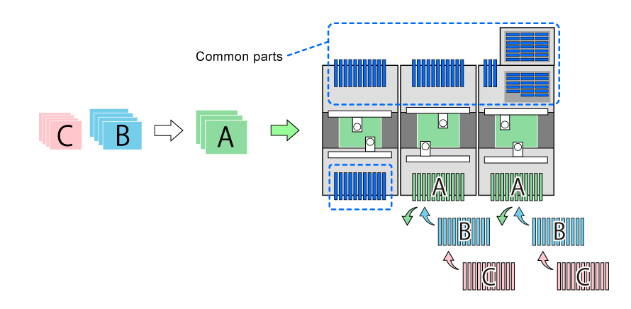
Product models (production programs) with many shared parts can be grouped together, and parts that differ between groups can be kept together on feeder pallets at specific machines to minimize the work routes used during changeover.
Preventing defects caused by supply mistakes - Top View Recognition
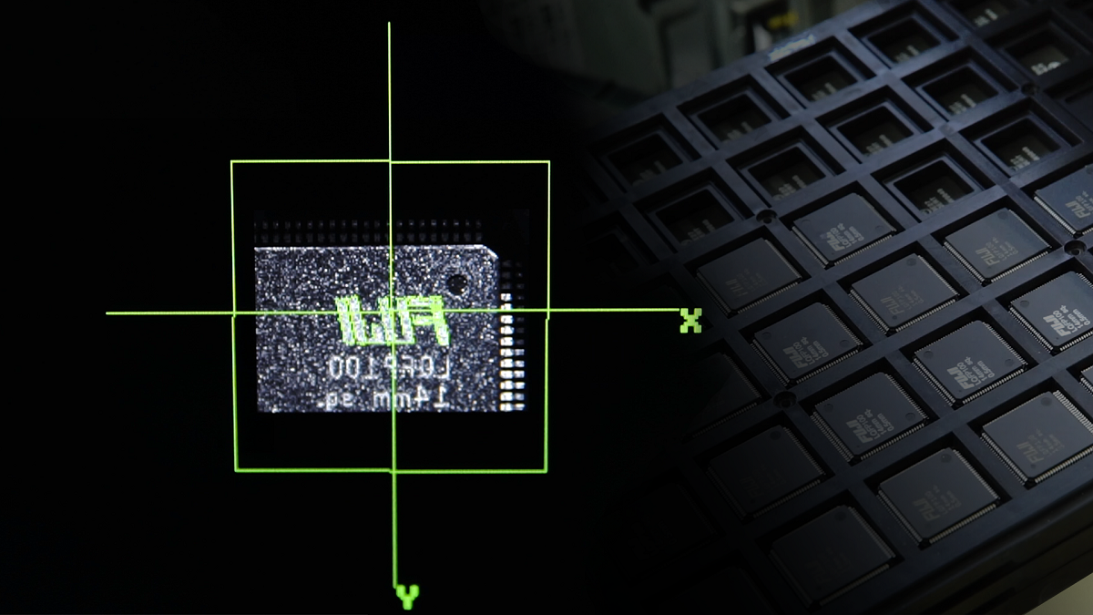
Unique features on the top side of parts, for example printing and marks, are recognized by vision processing to detect setting mistakes. After detection, it is possible to specify whether to correct or stop according to your operation.
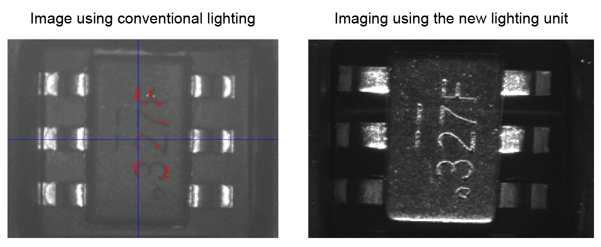
By installing a special lighting unit, even engraving such as laser markings that are difficult to recognize due to low contrast can be clearly imaged and recognized.
Note: Applicable machines: AIMEX III、AIMEX IIIc
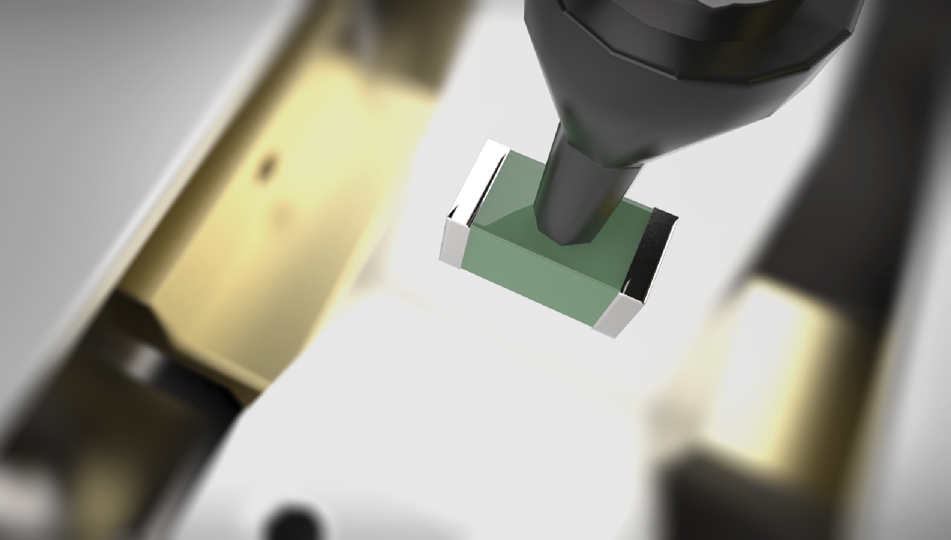
Checking the quality of packages - 3D coplanarity

This detects problems with packages and connector leads, and problems with the bumps on BGAs. It is possible to prevent defective contact caused by warp in large BGAs because this method even detects deformation in the Z direction that is difficult to detect using part cameras.
Check points
· Lead bending in the Z direction
· Collapsed bumps
Preventing the incorrect parts from being placed by checking their electrical properties - LCR check
The LCR value is checked automatically in the placement machine without human intervention.
Even in the unlikely event that an incorrect part is set in the feeder, the system can reliably detect and prevent placing these incorrect parts.
Measurement timing
· When starting and resuming automatic operation
· When resupplying parts
· During periodic checks
Maintaining quality by linking with inspection machines - Printer feedback control and mounter feedback control
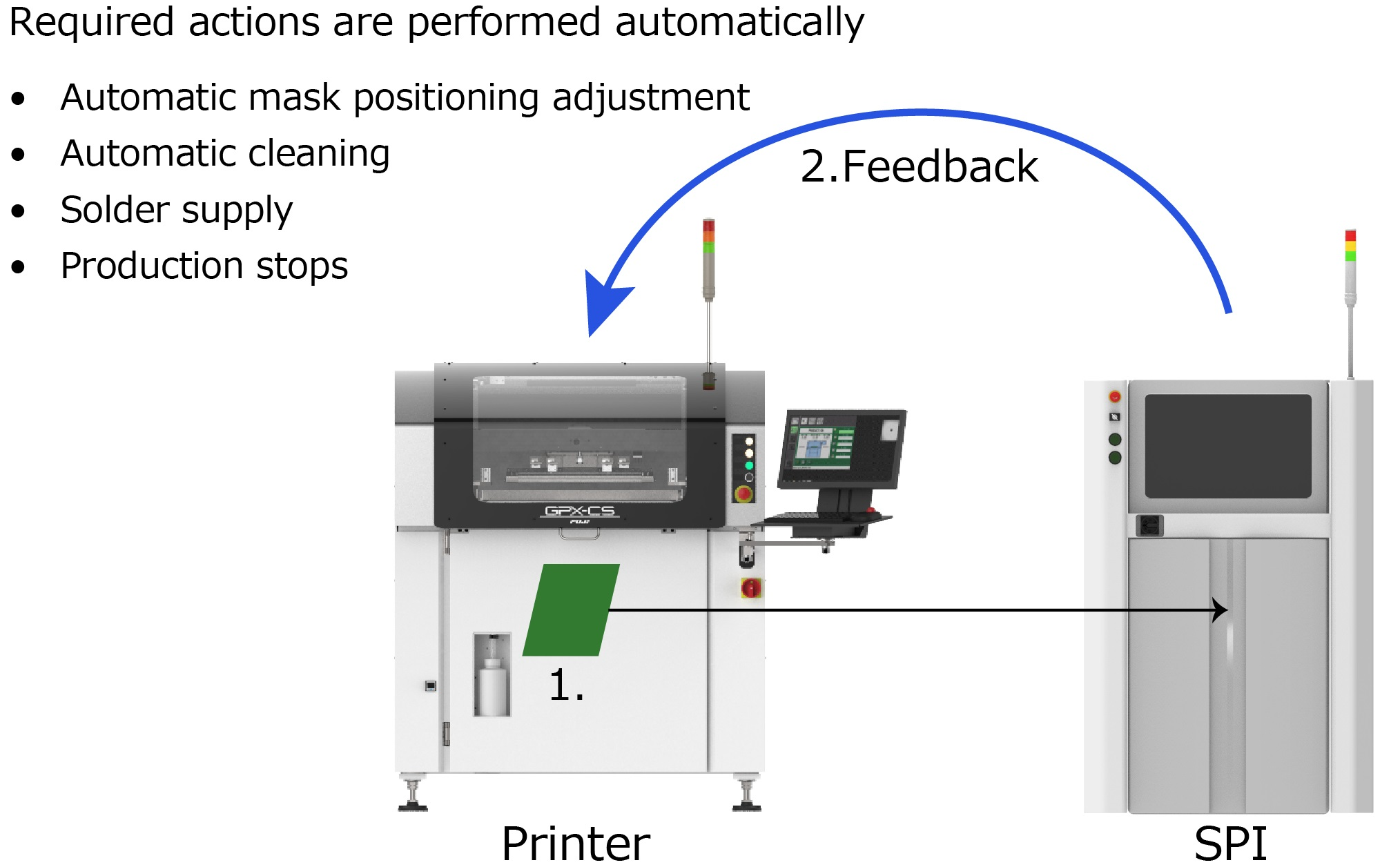
Printer feedback control
Inspection results are received from the SPI, and the appropriate response to trends that show a change in conditions can be performed automatically.
High-quality solder printing can be maintained because actions are taken before the specified tolerance values are reached.
Automated action through printer feedback control
· Mask position correction
· Automatic cleaning
· Solder supply
· Production stop
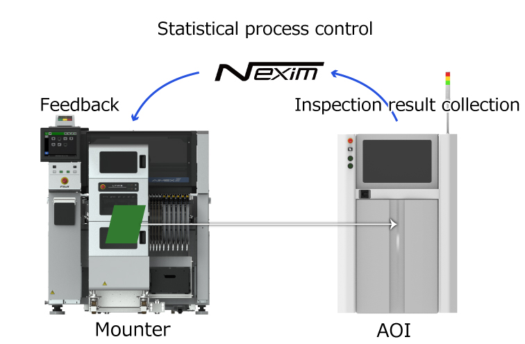
Mounter feedback control
If inspection results received from the AOI show a trend for a change in accuracy, the positioning is compensated automatically.
High-accuracy placement can be maintained because actions are taken before the specified tolerance values are reached.