


Have you ever experienced the following?
| · The wrong parts are picked due to parts looking too similar. |
| · Parts are checked in and managed using the wrong part ID because the wrong label was attached. |
| The wrong parts are used in high-volume production without noticing the mistake. |
| This results in... |
| Errors being discovered during conductivity tests. |
| · Large volumes of rework and wasted products. |
| · Damage to parts and panels. |
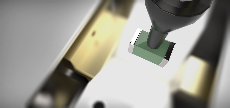
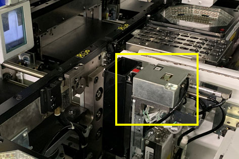
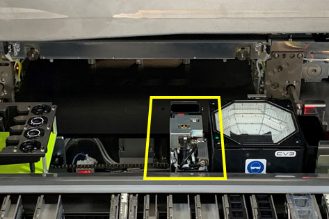
About LCR checks
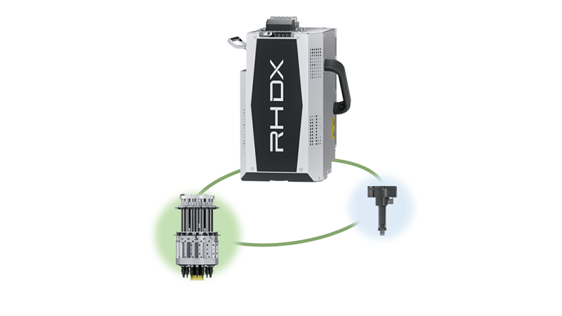
This is used to check whether the correct parts are set by measuring the LCR value of the first part in specified reels that have been newly set or replaced, or reels for which parts have been replenished by replacing the feeders or splicing tape.
The constant (LCR value) is checked before using the parts, thus preventing incorrect parts from being used.
Supported part types and measurement values
| Supported part types | Measurement values |
|---|---|
| Inductor (L) | Inductance coefficient value (H) |
| Capacitor (C) | Capacitance (F) |
| Resistor (R) | Resistance (Ω) |
Features of LCR checks
No part setting errors or measurement errors after measurement
Checks are automatically performed in the machine without operator work, which eliminates part setting errors and measurement errors after measurement.
It is possible to specify when to perform measurement Note 1
It is also possible to regularly perform measurement, in addition to the first part in reels that have been newly set or replaced, and reels for which parts have been replenished.
Measurement results can be acquired as traceability data Note 2
This helps daily quality control.
Note 1: Nexim only
Note 2: Option
Basic specifications
Two types are available according to the constants (LCR values) of electronic components.
| LCR | LCR2 - Type A | LCR2 - Type B | |
|---|---|---|---|
| Measurement range | Inductor 1 µH to 100 µH (±20%) Capacitor 1 nF to 1 µF (±10%) Resistor 1 Ω to 10 MΩ (±5%) |
Inductor 200 nH to 1000 µH (±20%) Capacitor 1 pF to 500 µF (±10%) Resistor 0Ω, 100 mΩ to 100 MΩ (±5%) |
Inductor 200 nH to 1000 µH (±20%) Capacitor 1 pF to 500 µF (±10%) Resistor 0Ω, 100 mΩ to 100 MΩ (±5%) |
| Supported part sizes | 0603 (0201") to 6 × 6 mm (thickness 0.2 to 3 mm) | 0603 (0201") to 6 × 6 mm (thickness 0.2 to 3 mm) | 0402 to 6 × 6 mm (thickness 0.2 to 3 mm) |
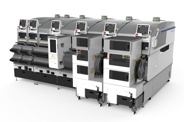
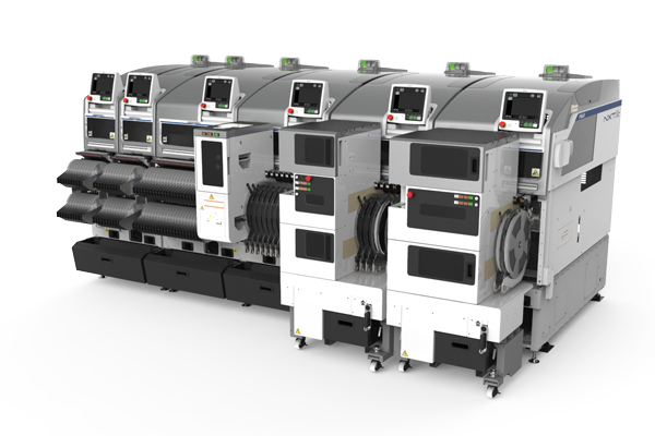
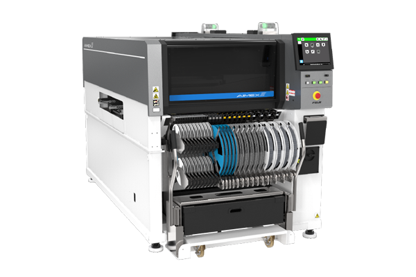
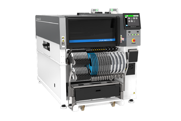
| Supported machine types | NXT II, NXT IIc, NXT III, NXT IIIc, AIMEX II, AIMEX IIS, AIMEX III, AIMEX IIIc | NXT III, NXT IIIc, AIMEX III, AIMEX IIIc | NXTR, AIMEXR |
| Supported heads | H08, H08M, H12HS, V12, H24(G), DX(R12) | H08(Q), H08M(Q), H12HS(Q), V12, H24, DX(R12) | RH28, RH20, RH08 |
| Required software | FUJI Flexa, Nexim | FUJI Flexa, Nexim | Nexim |
For more details, please feel free to contact us using the contact form below.